Specialized Tools for Electrophysiology and Cell Biology Research
- Customer Service: 800-232-2380
- Sales: 833-668-8632

EPC 10 USB - Heka Patch Clamp Amplifiers
Product Summary
The EPC 10 USB patch clamp amplifier, combined with a computer and PATCHMASTER software is a fully equipped recording setup.
- Computer controlled via PatchMaster Software
- Integrated data acquisition
- Three headstage configurations available
- Available in Single, Double and Quadro versions
The information shown here was collected from the HEKA Elektronik website.
We invite you to contact them for advanced technical and sales support.
Models and Features
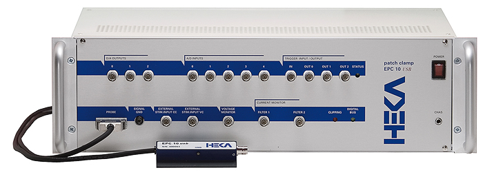
EPC 10 Single
EPC 10 USB Single Patch Clamp Amplifier – The EPC 10 USB is a complete data acquisition system, which can be used with HEKA’s PatchMaster software. A DLL (dynamic link library) is available for software developers who are interested in writing their own Windows data acquisition software.
The EPC 10 USB patch clamp amplifier, combined with a computer and PATCHMASTER software is equivalent to a fully equipped recording setup, which includes a patch clamp amplifier, a digital storage oscilloscope, a variable analog filter, a sophisticated pulse generator, and a full featured data acquisition and analysis system.
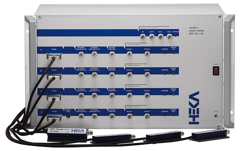
EPC 10 USB Double and Quadro
The EPC 10 USB Double and Quadro amplifiers are the optimal instruments for performing multiple patch/cell experiments. Although two, three or four amplifiers are combined in a single housing, along with the built-in LIH 8+8 interface, each amplifier is completely independent. The amplifiers and headstages are clearly identified, so the user can immediately assign the amplifiers to particular patched cells. The PatchMaster software can simultaneously stimulate and acquire the response from each amplifier. Current and/or voltage signals from all of the amplifiers can be recorded, displayed and analyzed online.
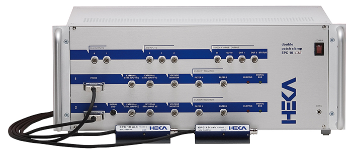
The EPC 10 USB Double and Quadro amplifiers also provide an economical solutions in comparison to a combination of several individual instruments. They also have advantages of optimized noise performance, grounding, data acquisition and data storage, convenience and ease of integration over multiple external amplifiers.
Headstages
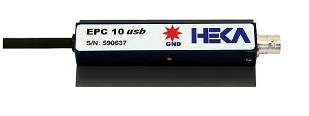
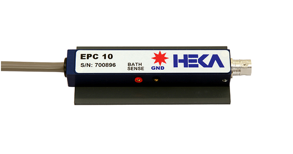
Red Star Headstage
All EPC 10 USB patch clamp amplifiers are now shipped standard with the Red Star Headstage with improved noise performance. Especially the most relevant bandwidth between 1 and 10 kHz is now significantly improved.
RMS noise values, Red Star Headstage EPC 10 vs. EPC 9
- Headstage:
- 1 kHz 31 fA vs 35 fA
- 3 kHz 72 fA vs 90 fA
- 5 kHz 120 fA vs 150 fA
- Features:
- Improved noise performance in the important 1 – 10 kHz band
- Three feedback resistors for three gain ranges, switchable during the experiment
- Optimized for single-channel and whole-cell recordings
- Retrofittable on older EPC 10 amplifiers
S-Probe
The unique feature of the S-Probe is the small size (49 x 16.5 x 14 mm) and weight (24g) compared to any other headstages. This increases the area of applications e.g. wherever the experimental space is limited or where the weight of the headstage itself matters. The cable is very flexible and therefore prevents cable stress.
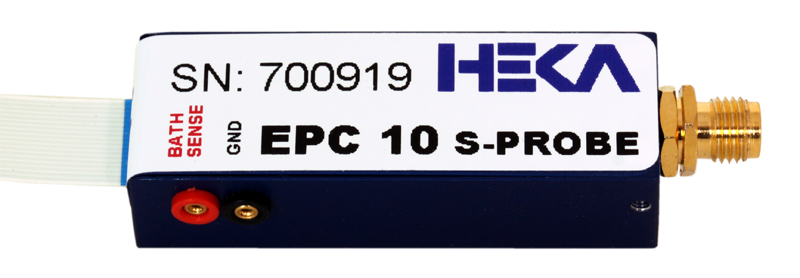
The electrical specifications of the S-Probe are identical to our standard Red Star Headstage. In addition it has the feature of an optional bath sense connection which gives it the opportunity to operate in the 3 Electrode Mode.
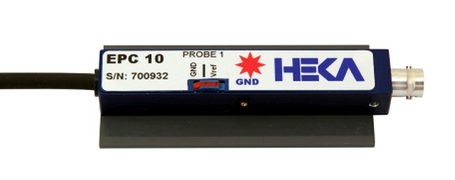
3-Electrode Mode Headstage (Optional)
With the 3-Electrode Headstage the EPC 10 USB can measure the potential difference between a third electrode (reference) and the ground (counter) electrode without having current flowing through the reference electrode. The reference electrode stays in equilibrium! The potential difference is added to the command potential for the working electrode.
With the 3-Electrode Mode Headstage, the EPC 10 USB patch clamp amplifier has the performance of a high-end potentiostat/galvanostat with a scan range of ± 2 V.
Patch Amperometry Headstage (Optional)
The detection of released substances from cells as oxidation current at carbon fiber electrodes is often directly combined with electrical measurements from cells.
A typical measuring configurations is patch amperometry combined with on-cell capacitance measurements.
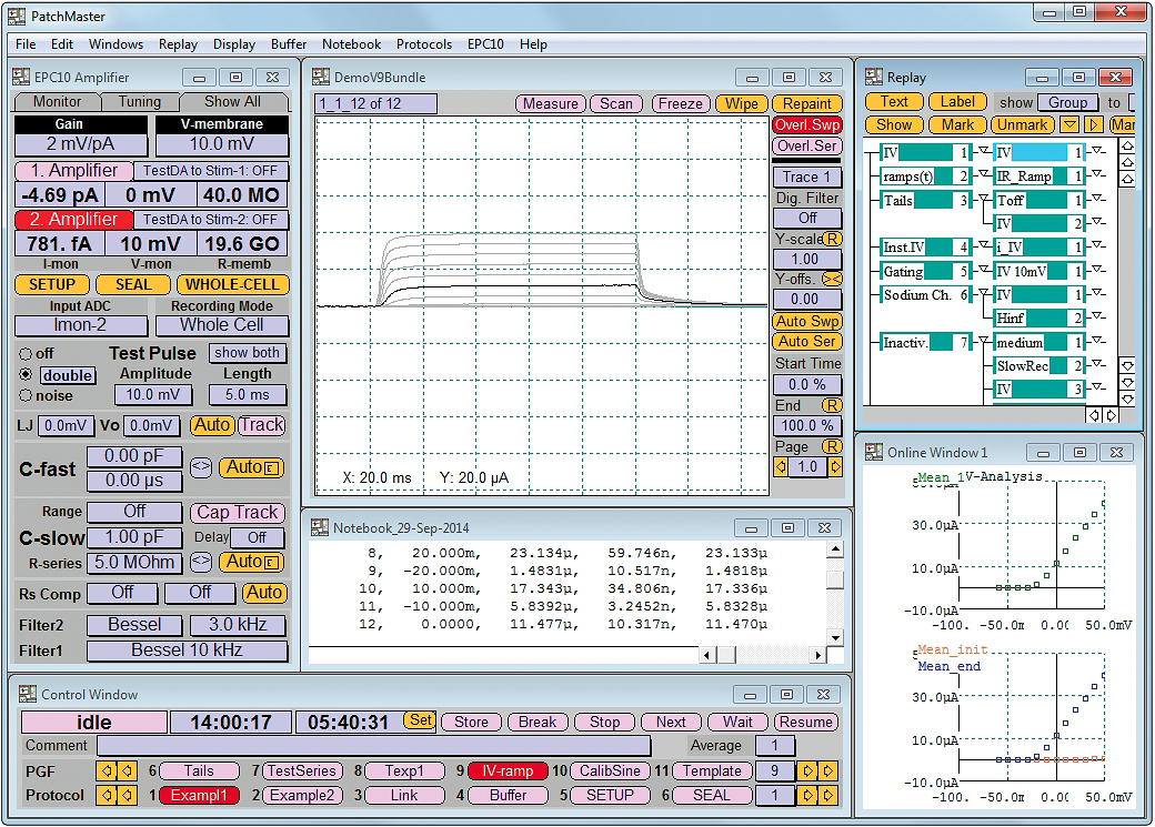
PATCHMASTER Software
PATCHMASTER is a multi-channel stimulation/acquisition and control software. The EPC 10 USB family of amplifiers is controlled using this software on either Windows (XP, Win7, Win8, Win10) or Mac (OS X 10.4+) platforms. For more details please refer to the PATCHMASTER brochure.
PATCHMASTER NEXT
PATCHMASTER NEXT is a versatile toolkit for electrophysiological and electrochemical experiments. It provides multi channel stimulation and data acquisition with integrated online and offline analysis features.
PATCHMASTER NEXT is a driving program for amplifiers, especially with controlling features for EPC 10 USB (Single, Double, Triple and Quadro) amplifiers. Further, surrounding components like temperature controllers, perfusion systems or other third-party devices can be managed by PATCHMASTER NEXT.
One of the biggest changes you might immediately realize when starting PATCHMASTER NEXT the first time is its change in the graphical user interface. The change in the graphical user interface and the preserved workflow should facilitate the transition of new and old PATCHMASTER users to PATCHMASTER NEXT.
PATCHMASTER NEXT orginates from the PATCHMASTER software and represents the next level of development of our famous patch clamp software. The first versions of PATCHMASTER NEXT may not include new features but intends to cover the full functionality of its precursor in a short time. Thereafter, we will include more new features and alleviations to make it even more powerful.
General |
|||||||||||||||||||
| Number of Amplifiers/Headstages | |||||||||||||||||||
| EPC 10 USB Single EPC 10 USB Double EPC 10 USB Quadro |
1 2 4 |
||||||||||||||||||
| Amplifier Control | Fully software controlled patch clamp amplifier featuring e.g. direct access to all amplifier settings, automatic calibration and self testing/diagnosis procedures. | ||||||||||||||||||
| Host Interface | USB 2.0 | ||||||||||||||||||
| Dimensions Main Unit | |||||||||||||||||||
|
|||||||||||||||||||
| Weight Main Unit | |||||||||||||||||||
|
|||||||||||||||||||
| Headstage Dimensions | D x W x H: (90 x 17 x 14.5) mm / (3.54 x 0.67 x 0.57) inch | ||||||||||||||||||
| Power Supply | Power requirements are 125 Watt. The logic controlled power supply automatically switches the voltage range. It operates in the ranges 90 V to 120 V and 210 V to 250 V at line frequencies of 50 or 60 Hz. A shielded transformer minimizes noise pickup from power line frequencies. | ||||||||||||||||||
| Ground Lines | A Signal ground is accessible via a Banana plug on the front panel of the main unit and via a connector pin on the headstage. In case of EPC 10 Double and Quadro, all amplifiers share the same ground. A Chassis ground is accessible via a Banana plug on the front panel of the main unit. Chassis and Signal ground are connected via a 10 MQ resistor. |
||||||||||||||||||
Voltage Clamp Mode |
|||||||||||||||||||
| Current Measuring Resistors | The headstage provides three feedback resistors. The gain ranges can be switched during the experiment. | ||||||||||||||||||
|
|||||||||||||||||||
| Current Gain Settings |
|
||||||||||||||||||
| Input Capacitance | < 1 pF | ||||||||||||||||||
| Noise performance | Measured with open input via external 8-pole Bessel filter. | ||||||||||||||||||
| Medium gain range: |
|
||||||||||||||||||
| High gain range: |
|
||||||||||||||||||
| Bandwidth | 100 kHz (low and medium gain range), > 60 kHz (high gain range) | ||||||||||||||||||
| Current Filter | Filter 1 is a 6-pole Bessel pre-filter with 10 kHz, 30 kHz, 100 kHz, and HQ 30 kHz. The EPC 10 USB Single and Double allow to directly sample the current signal of Filter 1. Filter 2 is a 4-pole filter with 100 Hz to 15 kHz bandwidth with selectable Bessel or Butterworth characteristics. Filter 2 is usable in series with Filter 1 or as separate filter for external signals. |
||||||||||||||||||
| Holding Potential | Software controlled holding within a ± 2000 mV range. | ||||||||||||||||||
| External Stimulus Input (VC) | Via a BNC connector at the front panel an external stimulus input can be added to the internal set holding potential. An external stim scaling circuit allows scaling of the external stimulus with a factor in the range of ±1.0. | ||||||||||||||||||
Compensations in Voltage Clamp Mode |
|||||||||||||||||||
| Pipette Offset Potential Compensation | Automatic or manual adjustment of the offset potential in the range ±200 mV. | ||||||||||||||||||
| Injection Capacitors | The C-Fast compensation signal is injected via a 1 pF capacitor. The C-Slow compensation signals are injected via a 10 pF capacitor in medium and low gain and via a 1 pF capacitor in high gain range. | ||||||||||||||||||
| C-Fast Compensation | Automatic or manual compensation in all gain ranges: 0 to 15 pF, 0 to 8 µs tau (calibrated) 0 to ~80 pF (Extended C-Fast) |
||||||||||||||||||
| C-Slow Compensation | Automatic or manual compensation in all gain ranges: 0.2 to 1000 pF (low and medium range) 0.2 to 100 pF (high range) Rs range 1 MO; to 1 GO;. |
||||||||||||||||||
| Synchronous C-Slow Compensation | The EPC 10 USB Double and Quadro provide the option for synchronous C-Slow compensation pulses on multiple cells. This is essential for using the C-Slow compensation when measuring on multiple electrically connected cells. | ||||||||||||||||||
| Series Resistance Compensation | Maximal compensation is 95% with the optimal setting being dependent on the cell capacitance. Equivalent time constants: 2, 5, 10, and 100 µs |
||||||||||||||||||
| Hardware Leak Subtraction | Automatic or manual linear leak subtraction in all gain ranges: 0 to 2 nS (high range) 0 to 200 nS (medium range) 0 to 20 µS (low range). Injection time constant: 100 µs |
||||||||||||||||||
| Software Leak Subtraction | A versatile p/n leak subtraction is provided in combination with the PATCHMASTER software. | ||||||||||||||||||
Other VC Features |
|||||||||||||||||||
| Zap Pulse | Provided by the PATCHMASTER software. The amplitude (up to ±1 V) and duration is programmable. | ||||||||||||||||||
| Audio Resistance Monitor | A 3.5 mm jack is provided at the rear panel for connecting phones or speakers. Volume and Resistance/Frequency ratio can be adjusted by the PATCHMASTER software. Frequency range: 1 Hz to 10 kHz. |
||||||||||||||||||
Current Clamp Mode |
|||||||||||||||||||
| Current Injection | Four current injection gains are selectable: | ||||||||||||||||||
|
|||||||||||||||||||
| Voltage Gain |
|
||||||||||||||||||
| Voltage Filter | Filter 2 setting do also allow the filtering of the voltage signal in a current clamp measurement. | ||||||||||||||||||
| Voltage Measuring Range | The voltage measuring range is ± 1 V (± 5 V when using the “Extended Stimulus Range”) in current clamp mode. | ||||||||||||||||||
| External Stim Input (CC) | Via a BNC connector at the front panel an external stimulus input can be added to the internally set holding current. The scaling factor is determined by the selected current injection gain. | ||||||||||||||||||
| C-Fast in CC Mode | C-Fast is active in current clamp mode to allow voltage recordings at high bandwidth. | ||||||||||||||||||
| Bridge Mode | The voltage drop across the pipette resistance can be compensated. | ||||||||||||||||||
| Low Frequency Voltage Clamp (LFVC) | Automatic current tracking readjusts the holding current to fix any slow voltage drift while in current clamp mode. | ||||||||||||||||||
| Gentle Switch | When switching from voltage to current clamp, the holding current is automatically set to the “I-mon” in voltage clamp mode. | ||||||||||||||||||
| Fast Mode Switching | The PATCHMASTER software allows to rapidly switch between current and voltage clamp mode and vice versa during data acquisition. | ||||||||||||||||||
DA/AD Converter |
|||||||||||||||||||
| Stimulation |
|
||||||||||||||||||
| Free DA channels: |
|
||||||||||||||||||
| Free AD channels: |
|
||||||||||||||||||
| Digital Input/Output |
|
||||||||||||||||||
| Master/Slave Sync | 2 CAT5 connectors for synchronization of a second amplifier/interface system are provided at the rear panel. | ||||||||||||||||||
Related Files
Customers from Europe and Australia can use the Multi Channel Systems - Online Shop to order Warner products or create quotes.
| Order No. | Model No. | Product Description | USA Price | Order |
|---|---|---|---|---|
| Amplifiers | ||||
| 89-5000 | EPC 10 USB | EPC 10 USB patch clamp amplifier, Single | Login | Login |
| 89-5001 | EPC 10 USB Double | EPC 10 USB patch clamp amplifier, Double | Login | Login |
| 89-5003 | EPC 10 USB Quadro | EPC 10 USB patch clamp amplifier, Quadro | Login | Login |
| Accessories and Replacement Parts | ||||
| 89-5148 | HEKA pipette holder for S-Probe 1.0 mm | Login | Login | |
| 89-5149 | HEKA pipette holder for S-Probe 1.3 mm | Login | Login | |
| 89-5150 | HEKA pipette holder for S-Probe 1.5 mm | Login | Login | |
| 89-5151 | HEKA pipette holder for S-Probe 1.7 mm | Login | Login | |
| 89-5152 | HEKA pipette holder for S-Probe 2.0 mm | Login | Login | |
| 89-5227 | Heka BNC-style pipette holder, 1.0 mm | Login | Login | |
| 89-5228 | Heka BNC-style pipette holder, 1.3 mm | Login | Login | |
| 89-5229 | Heka BNC-style pipette holder, 1.5 mm | Login | Login | |
| 89-5230 | Heka BNC-style pipette holder, 1.7 mm | Login | Login | |
| 89-5231 | Heka BNC-style pipette holder, 2.0 mm | Login | Login | |
| 89-5214 | Connecting Cable Sub25 to 8 BNC/Adapter | Login | Login | |
| Software | ||||
| 89-5245 | PatchMaster Next | Login | Login | |
| 89-5046 | FitMaster | Login | Login | |
| 89-5247 | Dongle exchange (PatchMaster to PatchMaster Next) | Login | Login | |
| 89-5246 | Upgrade from Pulse to PatchMaster Next | Login | Login | |